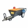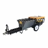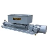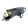
The basic structure of a plastering machine includes a winch mounted on a chassis with a vertical gantry and opposing scraper frames. A hopper connected to the chassis is installed inside the two uprights of the scraper frames. The hopper is slidably attached to the two uprights by the winch. A discharge port is located on one side of the gantry at the upper part of one end of the hopper, and a scraper is installed below the discharge port. Inside the hopper, a roller is supported along its width, and a motor is connected to the roller via a reducer. A feed port is located at the other end of the hopper. During operation, the roller pushes the material onto the scraper, and the winch lifts the hopper, allowing the paint to be evenly scraped onto the wall.
Newer indoor wall plastering equipment has a more complex structure, mainly including a support trolley, a feeding device, a support device, a coating device, and a recovery device. The feeding device includes a mixing component, a storage component, and a positioning component for mixing, storing, and conveying the material. The support device includes a guide component and a support component for supporting and driving the coating device to move up and down. The application device includes a plastering component and a drive component, responsible for applying plaster to the wall surface. The recycling device includes a recycling component and a plastering component, used to collect and reuse fallen plaster.
The automated plastering machine positioning system improves machine stability and precise control of plaster thickness. Its main structure includes a base and columns supporting the plastering mechanism. The lower end of the column passes through the base, and both its upper and lower ends are equipped with axially aligned locking electric push rods. The end of the column has at least two axially aligned guide studs, each with a slidingly engaging mounting plate. The locking electric push rods are fixed to the corresponding mounting plates. A compression spring is provided between the mounting plate and the guide studs. This system can fix the plastering machine body relative to the wall surface and achieve precise positioning of the distance between the base and the wall, and the relative position of the plastering mechanism and the wall.
Other related functional structures mentioned in the patents include lifting and adjustment systems, such as structures including a base plate, lifting device, gear rack, and hydraulic piston cylinder. There are also tilt adaptation structures that adjust the angle between the guide rod and the base plate via connecting components.